Technique Parameter
| Water-carrying caliber | Ф200 ± 0.6mm |
| Measuring range | ≤4mm / min (precipitation intensity) |
| Resolution | 0.2mm (6.28ml) |
| Accuracy | ± 4% (indoor static test, rain intensity is 2mm / min) |
| Power supply mode | DC 5V |
| DC 12V | |
| DC 24V | |
| Other | |
| Output form | Current 4 ~ 20mA |
| Switching signal: On-off of reed switch | |
| Voltage: 0~2.5V | |
| Voltage: 0~5V | |
| Voltage 1 ~ 5V | |
| Other | |
| Instrument line length | Standard: 5 meters |
| Other | |
| Working temperature | 0 ~ 50 ℃ |
| Storage temperature | -10 ℃ ~ 50 ℃ |
Wiring Method
1. If equipped with a weather station produced by the company, directly connect the sensor to the corresponding interface on the weather station using a sensor line; 2. If the sensor is purchased separately, as the sensor outputs a set of switching signals, the cable connector does not matter positive and negative. Connect the sensor to the circuit as shown in the figure.
MODBUS-RTU communication protocol
1. the serial format Data bits 8 bits Stop bit 1 or 2 Check Digit None Baud rate 9600 Communication interval is at least 1000ms 2. Communication format [1] Write device address Send: 00 10 Adress CRC (5 bytes) Returns: 00 10 CRC (4 bytes) Note: 1. The address bit of the read and write address command must be 00. 2. Adress is 1 byte and the range is 0-255. Example: Send 00 10 01 BD C0 Returns 00 10 00 7C [2] Read device address Send: 00 20 CRC (4 bytes) Returns: 00 20 Adress CRC (5 bytes) Explanation: Adress is 1 byte, the range is 0-255 For example: Send 00 20 00 68 Returns 00 20 01 A9 C0 [3] Read real-time data Send: Adress 03 00 00 00 01 XX XX Note: as shown below:| Code | Function definition | Note |
| Adress | Station number (address) | |
| 03 | Function code | |
| 00 00 | Initial address | |
| 00 01 | Read points | |
| XX XX | CRC Check code,front low later high |
| Code | Function definition | Note |
| Adress | Station number (address) | |
| 03 | Function code | |
| 02 | Read unit byte | |
| XX XX | Data (high before, low after) | Hex |
| XX XX | CRCCheck code |
RS485 circuit
Installation description
1. The installation position of the sensor can be selected on the ground, self-made big tube, iron pillar flange or on the roof of the house according to actual requirements. 2. Adjust the three leveling screws on the chassis to make the level bubble indication level (the bubble stays in the center of the circle), and then slowly tighten the three M8 × 80 fixing expansion screws; if the level bubble changes, you need to readjust. 3. Assemble and fix the sensor as shown in the figure above. 4. After fixing, open the rain bucket and cut off the nylon cable ties on the funnel, slowly inject fresh water into the rain sensor, and observe the turning process of the bucket to check whether the data is received on the acquisition instrument. Finally, quantitative water (60-70mm) is injected. If the data displayed by the acquisition instrument is consistent with the amount of injected water, the instrument is normal, otherwise it must be repaired and adjusted. 5. Avoid disassembling the sensor during installation.Selection Table
| No | Power supply | Output Signal | Instructions |
| LF-0004 | Rain sensor | ||
| 5V- | |||
| 12V- | |||
| 24V- | |||
| YV- | |||
| M | Switch signal output | ||
| V | 0-2.5V | ||
| V | 0-5V | ||
| W2 | RS485 | ||
| A1 | 4-20mA | ||
| X | Other | ||
| E.g.: LF-0014-5V-M: Rain sensor. 5V power supply, switch signal output | |||
Precautions
1. Please check whether the packaging is intact and check whether the product model is consistent with the selection. 2. Do not connect line with power on. Only check the wiring and make sure the power is on. 3. The sensor cable length will affect the output signal of the product. Do not arbitrarily place the components or wires that have been soldered when the product leaves the factory. If there is a need for change, please contact the manufacturer. 4. The sensor should be inspected regularly to remove dust, mud, sand, leaves and insects, so as not to block the water flow channel of the upper tube (funnel). The cylindrical filter can be removed and washed with water. 5. There is dirt on the inner wall of the dump bucket, which can be washed with water or alcohol or detergent aqueous solution. It is strictly forbidden to wipe with fingers or other objects, so as not to get oily or scratch the inner wall of the dump bucket. 6. During freezing in winter, the instrument should be stopped and can be taken back to the room. 7. Please save the verification certificate and the certificate of conformity, and return it with the product when repairing.If the sensor outputs other signals, the corresponding line sequence and function of the conventional sensor are as follows:| Line color | Output signal | ||
| Voltage | Current | communication | |
| Red | Power + | Power + | Power + |
| Black(green) | Power ground | Power ground | Power ground |
| Yellow | Voltage signal | Current signal | A+/TX |
| Blue | B-/RX | ||

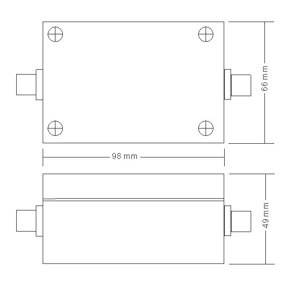
Structure Dimensions
Transmitter size

Troubleshooting
1. The display meter has no indication. The collector may not be able to obtain the information correctly due to wiring problems. Please check whether the wiring is correct and firm. 2. The displayed value of the display is obviously inconsistent with the actual situation. Please empty the water bucket and refill the bucket with a certain amount of water (60-70mm), and clean the inside wall of the bucket. 3. If it is not the above reasons, please contact the manufacturer.